
In The Box you have been undertaking a series of tasks completing a work booklet covering a number of areas. Using your notes from the session you need to create a reference manual for yourself.
Worksheet
Important Notes, Guidance and Rules When Working in ‘The Box’.
- Being aware of otherpeople in the space.
- Wear steel toe capped boots (Personal Protective Equipment)
- Run cables in a way to avoid trip hazards.
- When at height ensure that the space below you is clear.
- Always secure safety chains.
- No liquids other than bottled water.
- No food.
- No running.
- If using a smoke machine ensure fire alarm is de-activated ensure alarm is re-activated.
- Technicians responsible for fire safety.
- No working on your own if you need to go to the gantry.
- Use a footsman if using ladders.
- If using gantry ensure roof lights are on.
- Manual handling procedures apply. HSE guidance for employers in regard to manual handling.
- Only 6 people to be on gantry level at any one time due to max weight and fire exits.
- If turning og house lifgts to test laterns etc shour “going dark”. Also check gantry and other areas for people.
Power on Procedure
- Ensure the 13amp DMX socket is switched on.

DMX 13amp socket detail - As seen in the image the control for the main lights in the control room and the auditorium are the same.

Main Lighting Control - To turn the lights on we need to press and hold the top right button (1). This works as a dimmer type switch, so the lights gradually fade up, release the button when the desired level is reached.
- To turn off the lights we press and hold the bottom right button (2).
- There is a similar switch to this in the auditorium which will just control the lights in that space.
- DMX Lighting
- Main Truss (movable) Board
- This is the lighting board, to turn this on we just need to move the two breakers (1) on. If any of the breakers below these (2) are flipped (2a) then that lantern has failed. The numbers next to these breakers refer to what channel that lantern is on. This is known as a hard wired system. As these channels are permanently installed in the theatre and the positions are unlikely to change. There is a little play due to length of cables at the ‘business end’ for actual lantern location.

Lighting Board. 1 – Main Breakers 2 – Channel Breakers 2a – Failed channel breaker
- This is the lighting board, to turn this on we just need to move the two breakers (1) on. If any of the breakers below these (2) are flipped (2a) then that lantern has failed. The numbers next to these breakers refer to what channel that lantern is on. This is known as a hard wired system. As these channels are permanently installed in the theatre and the positions are unlikely to change. There is a little play due to length of cables at the ‘business end’ for actual lantern location.
- Patch Bay Truss – Rear (Static) Truss board
- Turn large breaker to on position.

DMX 13amp socket detail - This will turn on the patchbay positoned above the breaker.

DMX Patch Bay - Once the breaker is powered we can then plugin power cables for the correspondingDMX channels. Each cable is numbered.

DMX patchable power cables
- Turn large breaker to on position.
- Main Truss (movable) Board
- Audio power on
- On the Dennon amp push the power button.

Dennon AMP Close-up detail
- On the Dennon amp push the power button.
Using the truss
- Make sure no one is below you and area is clear.
- Make sure cables are down.
- Ensure nothing is wrapped around the chains at locations 5,6,7,8 on diagram below.
- Put sign on entrance door stating that overhead work is in progress.
- Have a second person on ground floor.
- Have a person on the entrance doors.
- When lowering shout “truss down”, When raising shout “truss up” await confirmation replies from 2 banksman.

On the gantry located near position 7 of the diagram above is the truss controll board.
Truss controls explanation to go here with photo
- Twist emergency stop button to release it.
- Turn breakers on (pushed towards wall)
- Use switches 5,6,7, and 8 to ensure level ascent/descent.
- Ascent – Green LED – switch toward wall.
- No movement – no LED – Switch in middle position.
- Descent – Red LED – Switch toward gantry/self.
Rigging Lanterns Safely
- Where possible prep the lantern on the ground.
- Visually inspect the lantern looking fopr any damgae to cables, barn doors, scorch marks also check moving parts such as focus to ensure free movement. Don’t forget the plug. there should also be a ‘Portable Appliance Testing‘ (PAT) tested sticker on the unit. which should look similar to the one shown.

- Check the clamp and associated fixtures to ensure they are not loose but will enabling positioning later. Obviously some of these controls may be easily accessible once rigged.
- Check lantern has a safety cable (some fresnel require a safety chanin on their barn doors).
- If the above are fine then if possible test the light at ground level.
- If these checks fail do not rig the lantern.
- install gels and gobos.
- open shutters or barn doors if appropriate.
- If possible lower truss to a comfortable working height shoulder/chest height.
- Hook lantern onto the bar and tighten bolt. Do not place lantern on the truss at welding points this area is weaker than the rest of the truss and is also uneven so can cause the lantern to wobble.
- Secure safety cable, if the chain is long you can wrap the cable around the truss to ensure a good fit. This needs to be loose enough to enable movemtn and focusing of the lantern. The wrapping means that if the clamp does fail the lantern doesn;t fall far enough to pick up enough inertia to break the cable.
- Some lanterns may have a specific orientation.
- As with the safety cable excess power cable can be wound round the truss, some area of ‘The Box’ have a truss shelf where cables runs can be laid however.
- Ensure that the power cable is not touching any hot parts of the lantern.
- Connect lantern to power.
4 main types of lanterns (name, photo, uses, accessories, moving parts)
Lantern is the generic name given to theare lights.

How to draw a lighting plan – including lighting symbols and the information needed on a plan
Lighting plans are a system of simple images to designate various lanterns.
A lighting plan can be simple or complicated but it is essential a means of communicating the location, type channels and colours to other members working on the performance. I’ve listed 3 aspects here but as earlier noted the plan can be as simple/complicated as you wish and can involve many aspects of the set-up.
Lighting plans can include –
- Address/channel number.
- Colour Gel.
- Lantern Type.
- Position on truss.
- Gobo.
- Direction can be via orientation of symbol or via text eg SR (Stage right), SL (Stage left), Upstage (back of stage), Downstage (front of stage).
- Focus.
- Show name.
- Venue.
- Date.
- Set.
- Location.
- Key – to describe what he symbols mean
We can also produce a separate sheet if further information is required.
At the moment we are just creating a very basic plan to introduce us the main symbols for the lanterns that we will be using as well as how to denote channels and colours.
Lanterns have specific symbols depending on the type, if we use software then we can get more detail into the plan as most software packages have simple diagrams for many different manufacturers and models. However for our purpose we will be sticking with the 4 main lanterns that we will be using in the box
- PAR

Parcan Symbols - Fresnel

Fresnel Symbol - Profile

Profile Symbol - Flood

Flood Symbol As can be seen some lannterns can have various smbols to denote them.
To denote the channel number we use a number surrounded by a circle

and to denote gels we either just write the number of the gel or the colour we desire.
Gobos we denote by placing a black dot in the necessary lantern symbol and we can also state its name and/or number, this can be seen in the profile image above.
Map of the main auditorium and roof space
the-box-blank-floor-pdfthe-box-blank-roof-pdfthe-box-lighting-plan
the-box-lighting-map – drawn notes
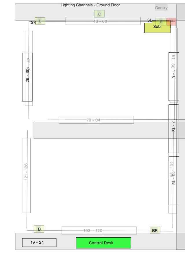

Upload a copy of your groups plan from the rigging session

For these plans I have used LXfree which is why some things look different. From with in the program I can choose some specific lights/models. The profiles – see the 2 green lights with gobos near the bottom of the image above are the symbol for source fours, there is no generic symbols for flood lights so I have used the symbol shown on channel 110. Speaking of channels the way the program displays channels is with the number in bold near that lantern. The number you can see in italics near on the bottom truss is the gel number and the colour within those lanterns is that colour gel. For the top truss where there are no italics they are just generic colours. This will probably be the way I will continue to do lighting plans, enabling me to learn the software as it does seem to have a lot of functionality.
